Design Your Own Home Wiring Layouts with These Basic Home Electrical Wiring Diagrams.
Domestic
electrical wiring may seem difficult to understand, but this article
will help through some specific home electrical wiring diagrams.
Fundamentals of Household Wiring
Are
you planning to move into a new house and feel pretty excited about
doing some innovative electrical wiring there all by yourself? The idea
sounds great as that gives you the freedom to customize the design for
home wiring layout, and also help in saving quite a lot of money. But
this is not possible before you are well versed with the basics of
electrical wiring and know exactly how to chalk out correct home
electrical wiring diagrams.
In this article we will get acquainted with the various general
electrical components, their symbols and also study the different
fundamental electrical wiring configurations normally involved in every
domestic the wiring. But before that, let’s briefly look at what
electricity is.
What is Electricity?
Electricity:
The power that we receive in our houses from power stations in the form
of alternating current and voltage is in fact the electricity. Any
electrical wiring is useless without electricity and thus it becomes the
life line of all electrical systems. Generally, these are either around
110 or 220 volts depending upon which part of the globe you are in.
Similarly its frequency will be approximately 60 and 50 Hertz
respectively. Its Main Line is termed as the Phase or Live while the
other receiving terminal is called the Neutral. It can be absolutely
FATAL to touch the Phase terminal whereas the Neutral is just the
opposite and won’t produce any effect.
-
(Click Image to Enlarge)

The Socket:
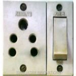
These can be seen in the form of AC MAINS power outlets over the
electrical boards. The power fed into a socket is always via a switch as
explained above. External appliances may be plugged into a socket and
switched ON to operate, and vice versa. Sockets are available in 2 or 3
pin types. In 3-pin types the third or the top pin is provided for the
earth or the ground connection. It helps in grounding or neutralizing
any dangerous residual electrical potential that may be hanging over the
connected appliance’s body.

Main DPDT Switch:
It may be considered as the entrance or the gateway for electricity and
thus has to handle huge loads. It’s also a kind of switch but is much
robust and designed to withstand high magnitudes of current through it.
DPDT stands for Double Pole Double Throw as these may be operated
manually to isolate both the wires of the supply line all at once for
ultimate safety (Refer Diagram). It also incorporates an in-built Fuse
to safeguard the whole house wiring in case of a short circuit.

Electrical Load:
Any electrical gadget that needs to be operated using electricity
constitutes an electrical load. Every piece of electrical equipment from
an incandescent bulb to the refrigerator that consumes electric power
to remain operative is an electrical load.
The next page will deal with the various home electrical wiring diagrams, so let's see how we proceed with them.
Designing Home Wiring Layouts
The following explanation will help you understand better how to design home wiring layouts:
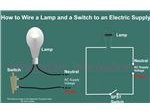
How to Wire a Switch and a Load (a Light Bulb) to an Electrical Supply:
As can be seen in the diagram the wiring is pretty simple. The Phase is
invariably applied to one terminal of the switch, the other terminal
moves to one of the connections of the load, and the other point of the
load continues to finish at the Neutral of the supply line. Toggling the
switch will alternately switch the bulb ON and OFF.
(Click Image to Enlarge)

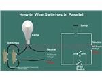
How to Connect Two Switches in Parallel to Operate a Single Load:
In the above example if an additional switch is connected to the
existing one in parallel, either of them may be used to switch ON the
bulb. And if desired, one switch may be located far away for remote
operation of the light. But here, to deactivate the load (Bulb), both
the switches will need to switch OFF.

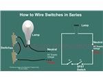
How to connect Two Switches in Series to Operate a Single Load:
If two switches are connected in series to the above network (see the
figure below)), both of them will need to be switched ON to energize the
load, but, toggling OFF any one of the switches will be enough to
extinguish the light.

How to wire a Socket with a Switch to an Electrical Supply:
The below given diagram shows a simple method of connecting a socket
with a switch. Here, the Phase as usual and mandatorily is connected to
one terminal of the switch and its other terminal is wired to the
RIGHT hand side terminal of the socket. The
LEFT hand side terminal of the socket goes to the Neutral line of the supply voltage.

How to Interconnect a Switch, a Fan and a Fan Regulator to an Electrical Supply:
With the help of the figure (shown below), one can easily see the
simple concept of joining a fan, a fan regulator and a switch to an
electrical supply. The idea is simple, just go on connecting each of
them in series to one another. The diagram is self explanatory
(Remember, the Phase always needs to be connected to the switch).
 electrical$ world
The
basic home electrical wiring diagrams described above should have
provided you with a good understanding. Hopefully this should help you
in designing your own home wiring layouts independently. If in any sort
of problem, feel free to exchange your thoughts with me (comments need
moderation, and may take sometime to appear).


