Basics of star delta1. Introduction
A contactor is a relay which
is capable of switching large
electrical loads.
Contactors and relays are
operated by applying a voltage to the coil of an Electro-magnet, which will
cause a switch, (or several switches) to close. The circuit that applies the
voltage to the coil is referred to as the control
circuit, because it controls the main device that the contactor or relay is
switching.
The coil voltage of a
contactor or relay can be installed for virtually any control circuit voltage,
to provide complete flexibility for these devices (both AC and DC), as the
control circuit can be completely independent of the load it is switching.
It should be noted that when
installing contactors or relays that you always check the coil ratings. They
often have not got a default rating of 230volts, and only go bang once if they
are connected to the wrong voltage!
This page explains how a
simple contactor (or relay) works, and describes some examples of how this
devices would control motor
2. Common relay/ Contactor set-up (utilising an emergency stop circuit)
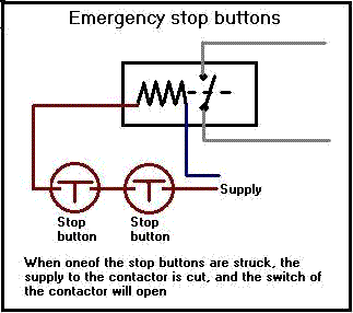
fig1.
The contactor is operated by
the control circuit energizing a coil, which can be controlled by any sort of
switching device (to perform an assortment of tasks). When the coil is energized,
the circuit that the contactor is switching will be energized.
In the above example, there
are two stop buttons (in brown - fig1) in the supply to the coil (black zigzag -
fig1). In the event that one of the stop buttons is struck, the circuit to the
coil will become broken, de-energizing the coil. The supply that the contactor
is switching (grey cables fig1) will therefore be switched off.
IMPORTANT : The above diagram
is designed to use lockable stop buttons only.
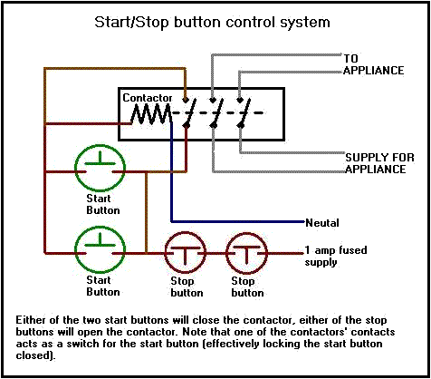
fig 2.
The contactor is operated by
the control circuit energizing a coil, as in the example above. When the coil is
energized, the circuit that the contactor is switching will be energized.
In the above example, there
are two start, and two stop buttons (in brown - fig2) in the supply to the coil
(black zigzag - fig2).
To close the contactor (to
energize the switched circuit), one of the two start buttons (in green - fig2)
must be pressed. Once the start button has been pressed, the contactor will
close, which will also close the 'lock' circuit to the contactor (holding the
supply to the coil).
To open the contactor (to
de-energize the switched circuit), one of the stop buttons must be pressed. The
circuit to the coil will become broken, de-energising the coil. The supply that
the contactor is switching (grey cables fig1) will therefore be switched off. (See
AC motor section at the bottom of this page).
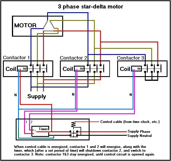
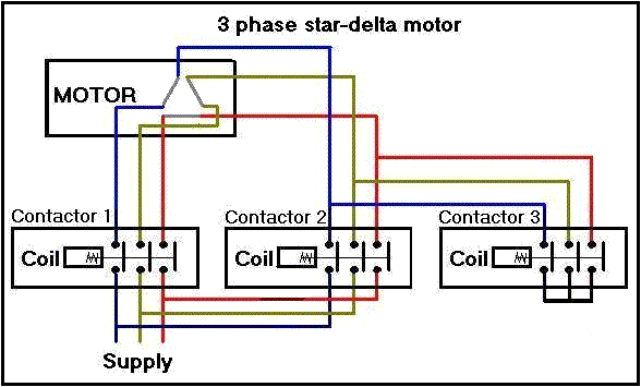
fig 3.
Star-Delta starting for
motors, utilises the same system as the previous example (fig 2), but
incorperates a method of changing the switching of the coils of a motor (while
it is in motion). NOTE: STAR-DELTA MOTORS HAVE 6 WINDINGS NOT 3 or 4.
When the start button is
pressed, contactor 1 and 3 will close. Contactor 1 will energise the 3 motor
windings on one end of the motor, while contactor 3 will bridge together the
cables from the other side of the motor (windings 4,5 and 6). This is STAR mode
running 230 volts per winding (see fig 4)...
A timer will be setup by the
installation engineer to provide enough time for the motor to get up to speed
properly in star mode. Once the motor is running, the time on the timer should
expire, making the Contactor 3 switch off, and changeover to Contactor 2
(Contactor 1 will also stay energised). (See AC motor section at the bottom
of this page).
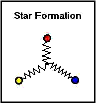
fig 4.
When contactor 2 has engaged,
the windings 4,5 and 6 will now also be supplying the motor, but at 120 degrees
from that of the supply to windings 1,2 and 3). ie... Winding 1 RED phase,
Winding 4 YELLOW phase, Winding 2 YELLOW phase, Winding 5 BLUE phase, Winding 3
BLUE phase, Winding 6 RED phase. This is DELTA mode, each winding has a 415v
supply across it. (see fig 5)....
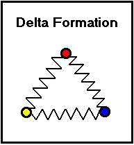
fig 5.
It is important to
remember that the coils of contactors come in allsorts of differing voltages, so
be sure that you are using the correct one for the job!
Remember to fuse the coil of
the contactor (and the control circuit itself) on its own circuit, as a coil
need only be fused at 1 or 2 amps.
Important.
If
using a control circuit using SELV (safety extra low voltages < 50volts) to control loads running on mains voltages, it is
essential that both the circuits are segregated from each other, to prevent
faults developing in the wrong circuits, the introduction of eddy currents in
the SELV wiring, and to prevent accidental wiring crossovers during maintenance.
7. Different types of AC Motors
Electric motors can come in many different forms, being controlled in many different ways.
This page covers AC single and three phase
motors.
Many of these motors are ‘contact less’
(ie, require no brushes), which gives them the advantage of having no parts that
produce sparks* or that are likely to be vulnerable to high
maintenance. *under normal operating conditions.
Common appliances such as electrical power
tools do however use motors that require brushes, as these motors are generally
lightly loaded, and are not used for prolonged periods of time. Motors used in these instances also need to be cost
effectively produced, which motors of this nature can be.
Speed controls can be applied to motors in
varying different ways, by either producing motors with differeing size windings
to ‘stage speed’ a motor, or to use frequency controls to physically
restrict the speed of the motor, by controlling the frequency of the supply
voltage (ie, a 50Hz supply will run faster than a 40Hz supply).
SINGLE PHASE DIRECT ONLINE MOTORS
The main types of motor you would find in
single phase equipment are direct on-line.
These motors consist of a single winding (the main winding) and a method
of starting the motor (the start winding or capacitor).
*for reference start windings refer to either a winding or capacitor.
Being single phase, this type of motor runs
at 230 volt.
AC motor windings alone are incapable
of starting themselves, and need a start winding to ‘shunt’ them in the
direction they are to run in (without the start winding, the motor will stall,
and eventually burn out due to over heating).
It is important to remember this principle
with these motors, because it is not possible to reverse the direction of travel
with a single phase direct on-line motor by changing the phase and neutral
supply to the motor. To reverse these motors, the start winding must have its
polarity reversed, with the main winding remaining unchanged.
3 PHASE DIRECT ONLINE MOTORS
The direct on-line 3 phase motor is used for
heavier work loads because these motors can provide substantially more torque
than its single phase equivalent. These
motors run on a 400v 3 phase supply, and can run using less current than an
equivalent single phase motor.
3 phase direct on-line motors consist of
three sets of windings (one for each phase), connected in delta.
These motors are connected directly to
either a 3 phase switch or a contactor (as a method of control).
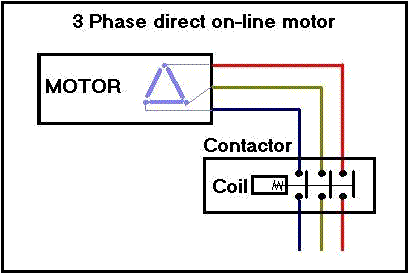
fig 6.
3 PHASE STAR-DELTA MOTORS
Three phase star-delta motors are
constructed similarly to a direct online single phase motor, but the terminals
for each winding are not terminated within the motor, instead they are brought
out of the motor for control wiring
to connect to.
Three phase star-delta motors are used for
maximum talk, where the motor will try to start under a heavy load. A star-delta
motor starts in two stages, controlled by equipment connected to it.
Stage one
The motor is required to start. To provide
the maximum available torque, the motor is started in ‘star’,
which provides a supply of 230volts to each of the windings (providing high
current to each winding).
Once the motor is running, it is running in
an inefficient mode, due to the use of a high current supply, which will (if
left) cause the motor to overheat.
Stage two
Once the motor is running, it no longer needs a high torque supply, so to save energy and
prevent the motor from destruction, the motor must change into a ‘delta’
configuration.
By changing the configuration of the motor
supply cables at the control equipment, the motor can be run in delta mode
(running each winding at 400volts rather than 230v, which uses less current)
No comments:
Post a Comment